ArcGIS Add-In Install Instructions
Add-In install instructions:
1. Download the latest Add-In file, provided by your FiberDock account manager
2. Open or double-click the .esriAddInX file to install it into ArcGIS Pro Or manually place it in: C:\Users\<username>\Documents\ArcGIS\AddIns\ArcGISPro
3. Restart ArcGIS Pro.
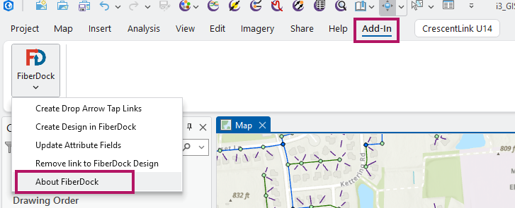
4. In ArcGIS Pro, under the Add-In tab/menu, select "About FiberDock" from the FiberDock drop menu. Verify that the version number displayed is correct.
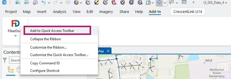
5. For easier access, add FiberDock to the Quick Access Toolbar.
The FiberDock menu can now be accessed from the top bar of ArcGIS Pro: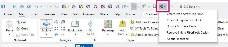
6. Before creating importing designs into FiberDock, ensure you have setup your login using the invite. If you don't see the invite email, please check your junk folder.
ArcGIS → FiberDock → CrescentLink Workflow:
Prerequisites: Layer for Drop Point Tap Links:
- The FiberDock ArcGIS Pro Add-In requires an additional feature layer to be added to your geodatabase.
- Ensure this layer has the same spatial reference as the Tap and Drop layers.
- Please add a line feature named DropPointTapLink. No attributes are required.
- This layer is only needed during the "Create Design in FiberDock" process and does not need to be saved, if that complicates things. So it need not be in your centralized geodatabase, or shared amongst your team.
- Verify that you are logged into the FiberDock Web App, and that you are on the latest release. You can see the latest release of FiberDock on the Release Notes page.
- To update to the latest version, hold the shift key, then click "Reload this page" in your browser.
- The feeder fiber start count is required, and will be entered into FiberDock in step 4 below.
Step 1. ArcGIS Add-In - Create Drop Arrow Tap Links:

In ArcGIS, ensure the sector is selected and click "Create Drop Arrow Tap Links" in the FiberDock menu. This will create "DropPointTapLink" features connecting each drop arrow to the closest tap endpoint. Please review these lines and ensure they connect the drop arrows to the appropriate tap. Correct any incorrect links.
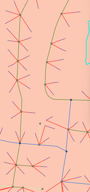
The drop arrow tap links can be seen in red, confirm they are connected correctly.
Step 2. ArcGIS Add-In - Create Design in FiberDock:

In ArcGIS, select the first splice point in the sector and select the "Create Design in FiberDock" menu option. Before creating the design in FiberDock, the Add-In will:
- Validate that the selected feature is a sdm_SplicePoint feature of subtype "Cabinet" or "Splice Case".
- If it is of subtype "Splice Case", validate that there must be one sdm_Cable feature starting in another sector, and ending at the selected Splice Case.
- Warn if any other cables between this sector and others are reversed (with start point at a sdm_SplicePoint in another sector, with end point in this sector). If not corrected, the reversed cables will be ignored.
- Warn if any sdm_SplicePoint features in the sector are not reachable due to a break in cable connectivity. If not corrected, any unreachable splice points and taps will be ignored.
- Validate that there is at least one "DropPointTapLink" in the sector.
The Add-In will then create the design in FiberDock.
Hint: If you see the error "Selected point must be either a Cabinet or a Splice Case with one cables starting in another sector.", verify the direction of the cable which feeds the starting splice point.
Step 3. FiberDock Web App - Design Properties Screen:
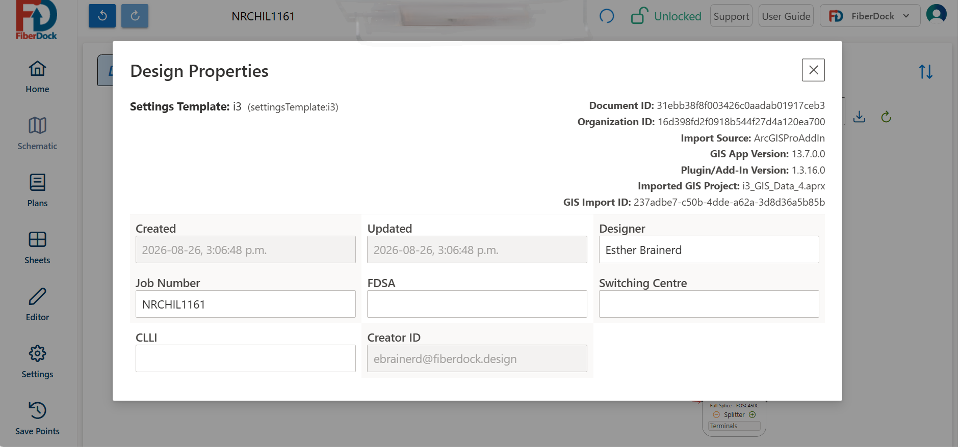
- Once your design is created in FiberDock, the Design Properties screen will appear.
- The Job Number will be filled in with the sector ID of the imported sector.
- You may fill in FDSA, CLLI and Switching Center (optional).
- Close the Design Properties screen to reveal the Schematic Screen.
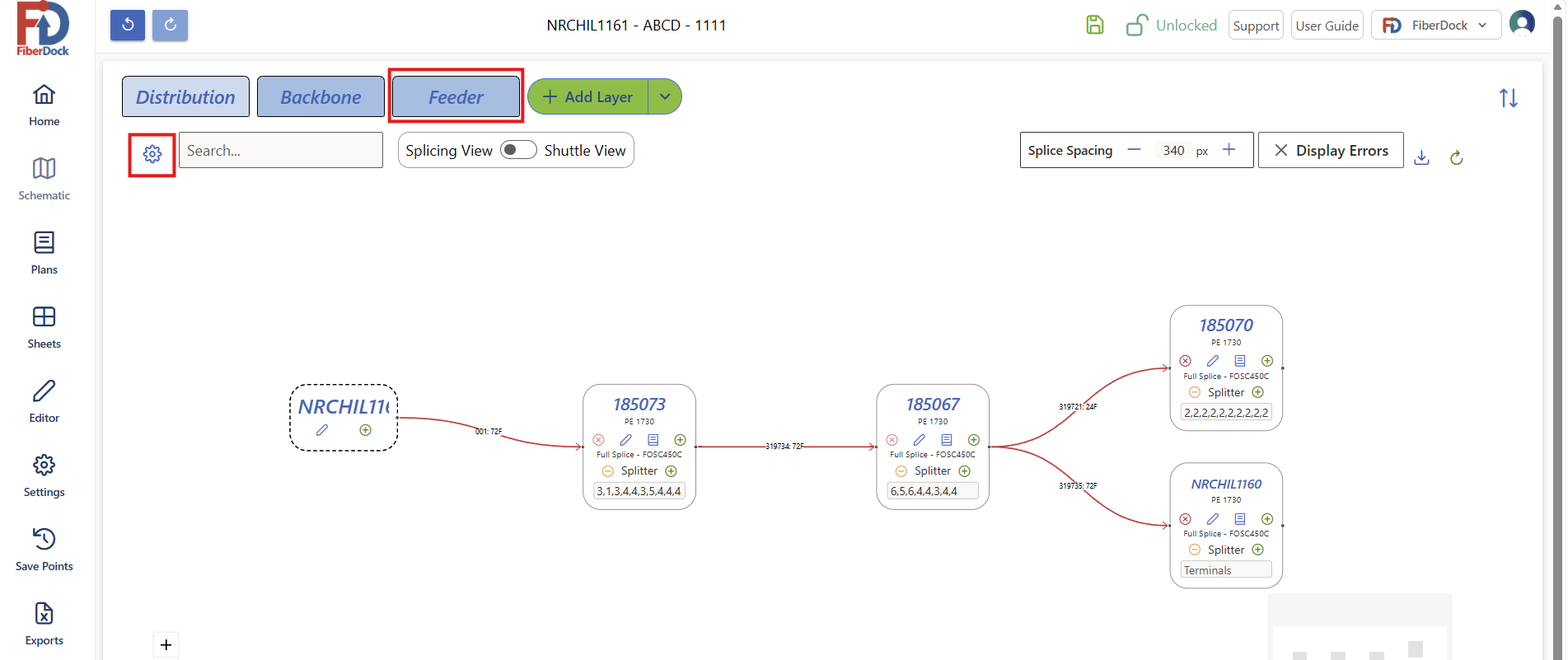
Step 4. FiberDock Web App - Assign the feeder fiber start count:
- Go to Schematic screen (if not already there).
- Click the Feeder tab.
- Click the gear in the top left to open the layer properties.
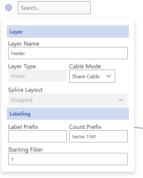
- Note that the Count Prefix will be filled in with the imported sector number. This value is used as the count prefix for counts in CrescentLink.
- Change "Starting Fiber" from 1 to the appropriate value.
Step 5. FiberDock Web App - Assign Splitters and Shuttle:
- Go to Schematic screen (if not already there).
- Ensure you are on the Distribution tab.
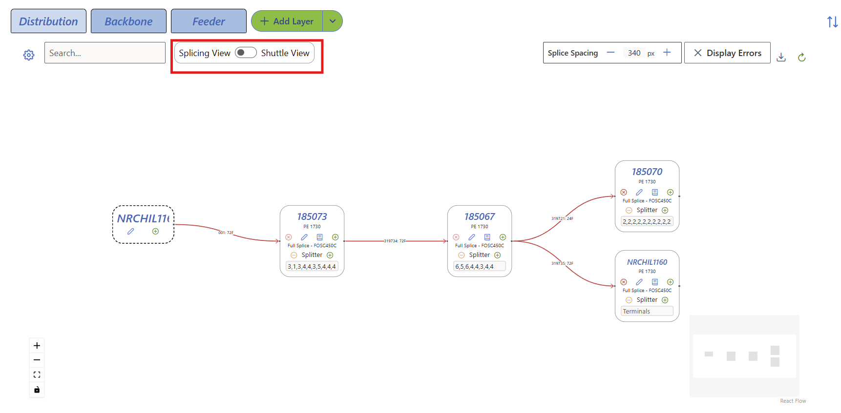
- Switch the view from Splicing to Shuttle view if necessary.
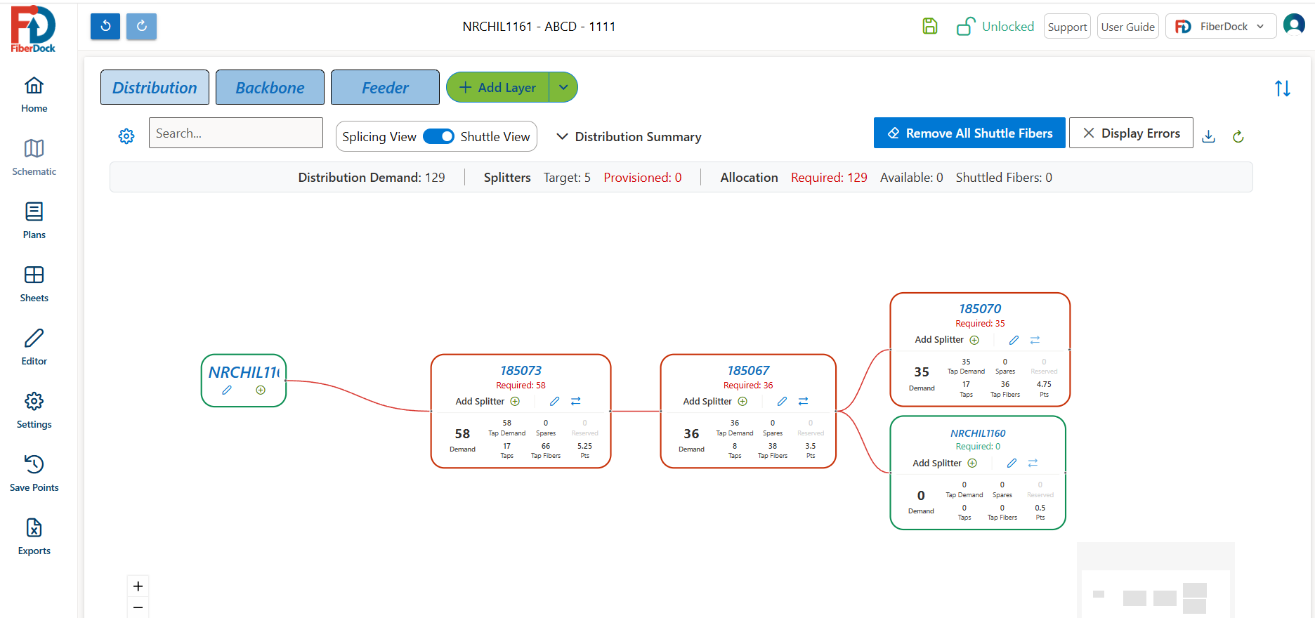
- Add splitters and shuttle fiber as required until all splice points are green.
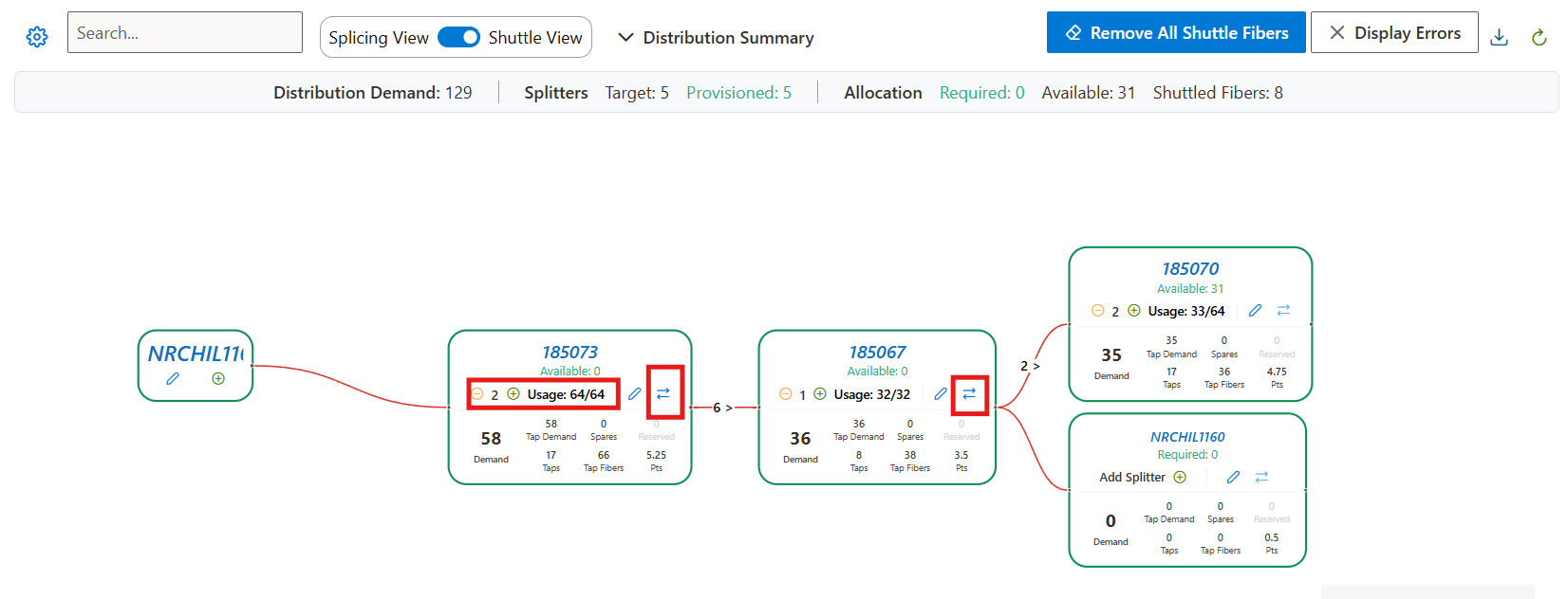
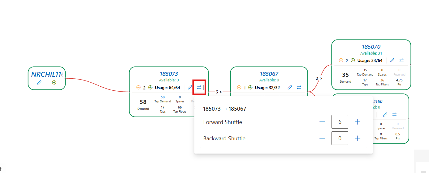
- You may now return to ArcGIS to import the FiberDock data.
Step 6. ArcGIS Add-In - Update Attribute Fields:

- In ArcGIS, select the sector you would like to update.
- Select the "Update Attribute Fields" FiberDock menu item.
- The Add-In will open a web browser to authenticate. You may close the browser screen after it opens.
- The Add-In will display a progress indicator as it updates the ArcGIS and CrescentLink values.
- Use the CrescentLink Network Manager and Connector tools to review the Equipment and cable connections that have been added.
- If you change the FiberDock design, you can run Update Attribute Fields again to see the updated values in CrescentLink.
Quick Start
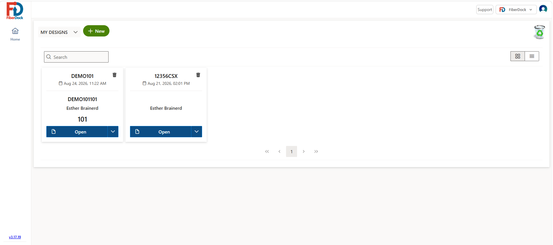
Home - Navigate through all of your designs and all designs within your organization, as well as move designs to your Trash bin.
The button above switches from looking at your designs to all the designs in your organization.

The button above creates a new design from scratch, opens a blank design.
 This button opens the trash bin of recently deleted designs
 This button allows a user to switch between two different views.
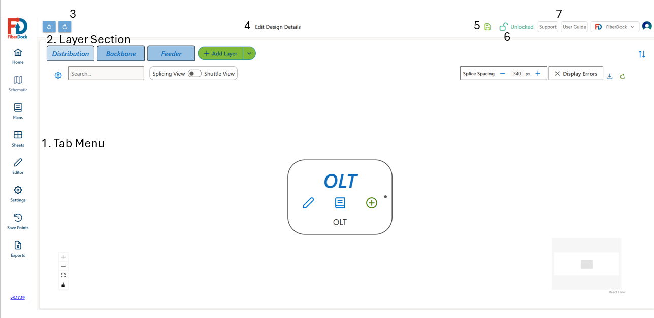
Tab Menu - Use the side menu to navigate through the 7 main features of FiberDock.
Home - Navigate through all of your designs and all designs within your organization, as well as move designs to your Trash bin.
Schematic - This is the Main section you can see above, at a high level you can create and edit your fiber network layer and edit shuttling.
Plans
Sheets - Splicing Sheets
Editor
Settings
SavePoints - Version Control for a design
Exports - PDF and Excel
2. Layer section - Edit and View Feeder, Backbone and Distribution layers independantly
3. Undo or move through edits
4. Edit Design Details - Job number, FDSA Switching center, CLLI
5. Check to see if your app is connected to the data base and actively saving your designs
6. Check access of a design. Lock - Only you can edit, Unlocked - anyone can edit, Frozen - no one can edit
7. Training Guide, or submit a help ticket
 This gear can be seen on all layer tabs, it is a setting section that allows users to edit labeling and layer information
 This allows a user to switch between Splicing View and Shuttle view.
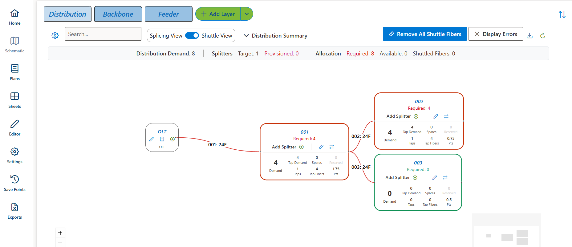
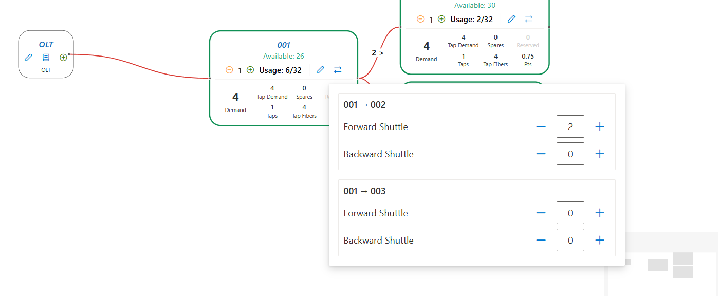
Shuttle View allows a user to balance there design by adjusting the splitter count 
or by adding forward or backward shuttle